Global web icon
sanfoundry.com
https://www.sanfoundry.com/timing-diagrams/
Timing Diagrams - Sanfoundry
Learn the basics of timing diagrams, their components, steps to draw them, flip-flop behavior, and practical applications in digital circuit.
Global web icon
ohio.gov
https://www.transportation.ohio.gov/wps/portal/gov…
Signal Design Reference Packet (SDRP) - Ohio Department of Transportation
The purpose of this packet is to provide guidance on designing and reviewing Traffic Signal, Pedestrian Hybrid Beacon, and Ramp Meter and other signal related plans. The format, legends, TEM tables/charts, page layouts, and sample details presented shall be used and followed as shown.
Global web icon
youtube.com
https://www.youtube.com/watch?v=AaxYMEnPexM
Sequential Circuit Design (State Diagram and State Table) - Part I
Learn what they are, how they represent sequential circuits, and discover the step-by-step process of generating a state table from a state diagram.
Global web icon
psu.edu
https://www.cse.psu.edu/~kxc104/class/cmpen270/10s…
Circuit, State Diagram, State Table - Pennsylvania State University
Circuit, State Diagram, State Table Circuits with Flip-Flop = Sequential Circuit Circuit = State Diagram = State Table State Minimization Sequential Circuit Design Example: Sequence Detector Example: Binary Counter
Global web icon
electrically4u.com
https://electrically4u.com/state-diagram-and-state…
State Diagram and state table with solved problem on state reduction
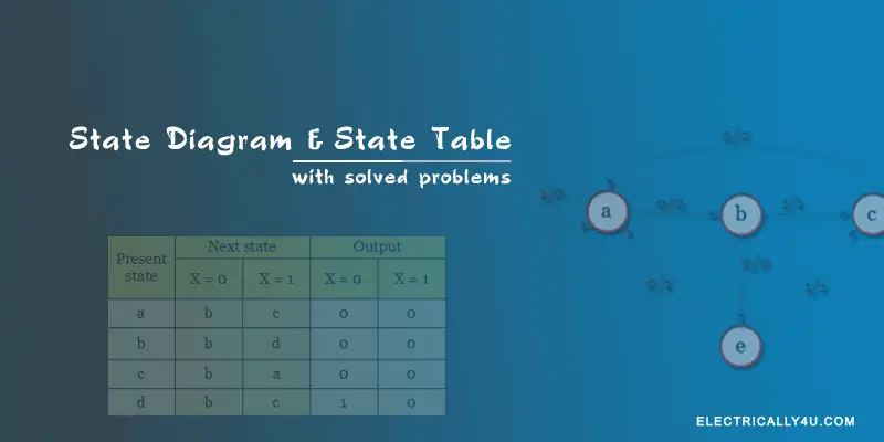
In this diagram, each present state is represented inside a circle. The transition from the present state to the next state is represented by a directed line connecting the circles.
Global web icon
circuitdiagram.co
https://www.circuitdiagram.co/how-to-draw-a-timing…
How To Draw A Timing Diagram For Circuit - circuitdiagram.co
To create a timing diagram, collect all the data associated with your circuit and its components. Start with the first component, such as a switch, and label each of its states – usually either “On” or “Off”. Then, draw a line for each of the states along the vertical time timeline.
Global web icon
next.gr
https://www.next.gr/tutorials/digital-logic-design…
Sequential Circuit Timing Diagrams | Tutorials on Electronics | Next ...
Timing diagrams for sequential circuits graphically represent the temporal behavior of signals in digital systems, capturing state transitions relative to clock edges and propagation delays.
Global web icon
timingdiagrams.info
https://www.timingdiagrams.info/
Timing Diagram Basics
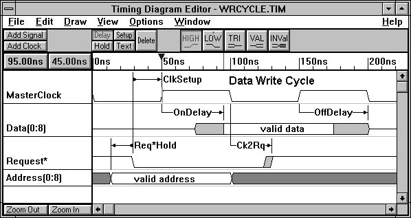
Timing diagrams show timing relationships between different signals inside an electronic circuit. They consist of signal waveforms and timing parameters like delays, setups, and holds. The waveforms show how the state of the signal changes with time.
Global web icon
maker.pro
https://maker.pro/custom/tutorial/how-to-read-timi…
How to Read Timing Diagrams: A Maker’s Guide | Custom
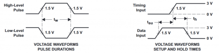
In this article, I’ll explain those diagrams and teach you how to read and interpret them easily!
Global web icon
electraschematics.com
https://electraschematics.com/what-is-timing-diagr…
Understanding the Basics of a Timing Diagram
In a timing diagram, time is typically represented on the horizontal axis, while the vertical axis represents different components or signals. Each component or signal is represented by a waveform, which shows its state over time.